
Transistor Switch
+6
lancemaximo
nicanorroberto
jin
aliahdelosantos
adrianmorcilla
Admin
10 posters
 AdminAdmin
- Posts : 17
Join date : 2017-09-20
Age : 26 
 Transistor Switch
Wed Sep 20, 2017 1:57 pm
First, we need to know what and how one of the main components needed works.
One of the most fundamental applications of a transistor is using it to control the flow of power to another part of the circuit - using it as an electric switch. Driving it in cutoff or saturation mode, the transistor can create the binary on/off effect of a switch.
What is a transistor switch?
Also, explain the low-side switch and high-side switch circuit.
Transistor Switching PNP
Transistor Switching NPN
Please be positive & constructive with your questions and comments. Thank you!
 adrianmorcillaGURU
- Posts : 12
Join date : 2017-10-03
Re: Transistor Switch
Tue Oct 03, 2017 9:12 am
Transistor switches are critical circuit-building blocks; they're used to make logic gates, which go on to create micro-controllers, microprocessors, and other integrated circuits.
- aliahdelosantosNEWBIE
- Posts : 2
Join date : 2017-10-11
Re: Transistor Switch
Wed Oct 11, 2017 6:55 am
Transisitor can be a switch when used as an AC signal amplifier, the transistors Base biasing voltage is applied in such a way that it always operates within its “active” region, that is the linear part of the output characteristics curves are used. However, both the NPN & PNP type bipolar transistors can be made to operate as “ON/OFF” type solid state switch by biasing the transistors Base terminal differently to that for a signal amplifier.
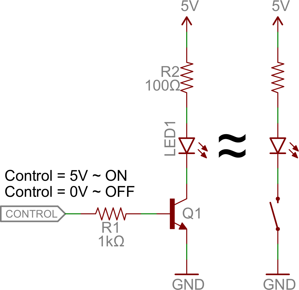
Solid state switches are one of the main applications for the use of transistor to switch a DC output “ON” or “OFF”. Some output devices, such as LED’s only require a few milliamps at logic level DC voltages and can therefore be driven directly by the output of a logic gate. However, high power devices such as motors, solenoids or lamps, often require more power than that supplied by an ordinary logic gate so transistor switches are used.
If the circuit uses the Bipolar Transistor as a Switch, then the biasing of the transistor, either NPN or PNP is arranged to operate the transistor at both sides of the “ I-V ” characteristics curves we have seen previously.
The areas of operation for a transistor switch are known as the Saturation Region and the Cut-off Region. This means then that we can ignore the operating Q-point biasing and voltage divider circuitry required for amplification, and use the transistor as a switch by driving it back and forth between its “fully-OFF” (cut-off) and “fully-ON” (saturation) regions as shown below.
- jinNEWBIE
- Posts : 1
Join date : 2017-10-11
Re: Transistor Switch
Wed Oct 11, 2017 3:55 pm
The transistor was invented by “William Shockley” in 1947. Based on what I've read, transistor work as a switch when it is in cutoff and saturation regions. The transistor has three terminals, namely Base, Emitter, and Collector. The emitter is a heavily doped terminal and it emits the electrons into the Base region. The Base terminal is lightly doped and passes the emitter-injected electrons onto the collector. The collector terminal is intermediately doped and collects electrons from the Base.
- nicanorrobertoNEWBIE
- Posts : 2
Join date : 2017-10-11
Re: Transistor Switch
Thu Oct 12, 2017 8:51 am
A Transistor switch, which is used for opening or closing of a circuit, that means the transistor is commonly used as a switch in the electronic devices only for the low voltage applications because of its low power consumption.
- AdminAdmin
- Posts : 17
Join date : 2017-09-20
Age : 26
Re: Transistor Switch
Thu Oct 12, 2017 8:53 am
What are the regions of operation of a transistor that is used for electronic switching?
- adrianmorcillaGURU
- Posts : 12
Join date : 2017-10-03
Re: Transistor Switch
Thu Oct 12, 2017 9:00 am
Ma'am that would be Saturation and Cut-off region.
- lancemaximoGURU
- Posts : 12
Join date : 2017-10-12
Re: Transistor Switch
Thu Oct 12, 2017 9:20 am
saturation region
cut-off region
Ma'am what's the difference between saturation and cut-off region?
cut-off region
Ma'am what's the difference between saturation and cut-off region?
- camillebungayMEMBER
- Posts : 4
Join date : 2017-10-12
Re: Transistor Switch
Thu Oct 12, 2017 10:25 am
Low-side switching means that the two subcircuits will have different ground levels since the switching element will have a (small) non-zero voltage drop.
High-side switching will have a lower maximum current limit since P-type (high-side) switching elements usually have a higher on resistance than N-type (low-side) switching elements.
High-side switching will have a lower maximum current limit since P-type (high-side) switching elements usually have a higher on resistance than N-type (low-side) switching elements.
- kaylefloresNEWBIE
- Posts : 2
Join date : 2017-10-12
Re: Transistor Switch
Thu Oct 12, 2017 6:25 pm
Maam I want to answer for lance's questions.
Saturation mode acts like CLOSE MODE of transistor while cut-off acts like an OPEN SWITCH.
Saturation mode acts like CLOSE MODE of transistor while cut-off acts like an OPEN SWITCH.
- AdminAdmin
- Posts : 17
Join date : 2017-09-20
Age : 26
Re: Transistor Switch
Thu Oct 12, 2017 6:36 pm
What is the control terminal of a bipolar junction transistor in transistor switching?
- AdminAdmin
- Posts : 17
Join date : 2017-09-20
Age : 26
Re: Transistor Switch
Thu Oct 12, 2017 6:39 pm
Lance, Mr. Flores did answer for your questions, Do you need more explanation?
You can visit this link. https://www.allaboutcircuits.com/textbook/semiconductors/chpt-4/active-mode-operation-bjt/
Comment if you have further questions.
You can visit this link. https://www.allaboutcircuits.com/textbook/semiconductors/chpt-4/active-mode-operation-bjt/
Comment if you have further questions.
- lancemaximoGURU
- Posts : 12
Join date : 2017-10-12
Re: Transistor Switch
Thu Oct 12, 2017 6:53 pm
What is the control terminal of a bipolar junction transistor in transistor switching?
MY ANSWER:
Input flows into the base and the collector for output and emitter is kept at fixed voltage.
MY ANSWER:
Input flows into the base and the collector for output and emitter is kept at fixed voltage.
- nathangonzalesMEMBER
- Posts : 3
Join date : 2017-10-12
Re: Transistor Switch
Thu Oct 12, 2017 7:05 pm
MAAM with the positive probe on an NPN base, what should be the ohmmeter reading between the other transistor terminals?
- AdminAdmin
- Posts : 17
Join date : 2017-09-20
Age : 26
Re: Transistor Switch
Thu Oct 12, 2017 7:08 pm
Nathan, I think the ohmmeter reading should be in low resistance.
Did you try testing it already?
Did you try testing it already?
- nathangonzalesMEMBER
- Posts : 3
Join date : 2017-10-12
Re: Transistor Switch
Thu Oct 12, 2017 7:11 pm
Yes maam, I thought it would be in high resistance, but its not. It's in low resistance . Thank you maam!
- AdminAdmin
- Posts : 17
Join date : 2017-09-20
Age : 26
Re: Transistor Switch
Thu Oct 12, 2017 7:20 pm
When transistors are used in digital circuits, they usually operate in the?
- adrianmorcillaGURU
- Posts : 12
Join date : 2017-10-03
Re: Transistor Switch
Thu Oct 12, 2017 7:28 pm
When a transistor is in the fully-off state (like an open switch), it is said to be cutoff. Conversely, when it is fully conductive between emitter and collector (passing as much current through the collector as the collector power supply and load will allow), it is said to be saturated. These are the two modes of operation explored thus far in using the transistor as a switch.
However, bipolar transistors don’t have to be restricted to these two extreme modes of operation. As we learned in the previous section, base current “opens a gate” for a limited amount of current through the collector. If this limit for the controlled current is greater than zero but less than the maximum allowed by the power supply and load circuit, the transistor will “throttle” the collector current in a mode somewhere between cutoff and saturation. This mode of operation is called the active mode.
An automotive analogy for transistor operation is as follows: cutoff is the condition of no motive force generated by the mechanical parts of the car to make it move. In cutoff mode, the brake is engaged (zero base current), preventing motion (collector current). Active mode is the automobile cruising at a constant, controlled speed (constant, controlled collector current) as dictated by the driver. Saturation the automobile driving up a steep hill that prevents it from going as fast as the driver wishes. In other words, a “saturated” automobile is one with the accelerator pedal pushed all the way down (base current calling for more collector current than can be provided by the power supply/load circuit).
- lancemaximoGURU
- Posts : 12
Join date : 2017-10-12
Re: Transistor Switch
Thu Oct 12, 2017 7:40 pm
When electromechanical relays were still used, inverse time relays, definite time relays, and instantaneous relays were separate relays.
Modern protection relays combine inverse time, definite time, and instantaneous characteristics into one device. So you can have all three types in one device.
Inverse time overcurrent relays: Slow to trip at low currents. Faster to trip at high fault currents. Used to co-ordinate over load protection, which may have a high starting current. Generally the most sensitive (lowest amps pickup), and slowest to operate.
Definite time relays: used to co-ordinate over other definite time, or instantaneous protection. Generally less sensitive (higher pickup) to prevent operating for load inrush. Generally faster operating time.
Instantaneous relays: Used when co-ordination is not required. Usually the least sensitive of all relays, as the relay must not operate for any kind of inrush, or operate before any downstream relay.
- ellislopezNEWBIE
- Posts : 1
Join date : 2017-10-12
Re: Transistor Switch
Thu Oct 12, 2017 7:49 pm
Types of protection:
Protection schemes can be divided into two major groupings:
Unit schemes
Non-unit schemes
1) Unit Type Protection
Unit type schemes protect a specific area of the system, i.e., a transformer, transmission line, generator or bus bar.
The unit protection schemes is based on Kerchief’s current law – the sum of the currents entering an area of the system must be zero. Any deviation from this must indicate an abnormal current path. In these schemes, the effects of any disturbance or operating condition outside the area of interest are totally ignored and the protection must be designed to be stable above the maximum possible fault current that could flow through the protected area.
2) Non unit type protection
The non-unit schemes, while also intended to protect specific areas, have no fixed boundaries. As well as protecting their own designated areas, the protective zones can overlap into other areas. While this can be very beneficial for backup purposes, there can be a tendency for too great an area to be isolated if a fault is detected by different non unit schemes.
The most simple of these schemes measures current and incorporates an inverse time characteristic into the protection operation to allow protection nearer to the fault to operate first.
The non unit type protection system includes following schemes:
(A) Time graded over current protection
(B) Current graded over current protection
(C) Distance or Impedance Protection
This is my answer for the question : When do we use IDMT relays and DTOC relays?
Permissions in this forum:
You cannot reply to topics in this forum